Pattern Modelling for Boots & Foot–Leg Measurements: Footwear Manufacturing Insights
Reading Time : 4 Minutes
This article continues the Footwear Manufacturing Insights technical series and is developed based on the provided reference images, following the same structured, professional, and instructional approach used in earlier blogs. It covers two essential topics for boot development:
- Pattern modelling techniques for boots
- Foot and leg measurements
Each topic is explained with manufacturing relevance, grading logic, and practical application for pattern makers and technical teams.


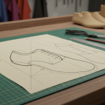
Pattern Modelling Technique for Boots
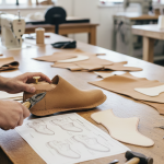
This section follows the referenced Modelling Technique material and presents the core pattern-making logic used in ladies’ boot development. The focus remains practical, direct, and suitable for factory application
Key Technical Points
First, draw the last form in the standard right-angle position to define both joint position and heel height accurately. Next, draw the leg direction line exactly at right angles to the base line, because this step directly controls shaft balance
In addition, the pattern maker must not rely only on last length. Instead, consider
- Boot width
- Lining type (unlined or plumped)
- Overall visual proportions

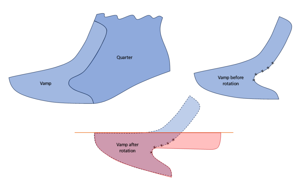
Insert-Based Modelling
Here, Vamp insert directly influences the visual appearance of the boot. Moreover, a complementary insert allows the upper components to combine without adding a central forepart seam.
After this, derive Vamp after Rotation from Vamp before rotation as shown in the image by placing it on the fold line.
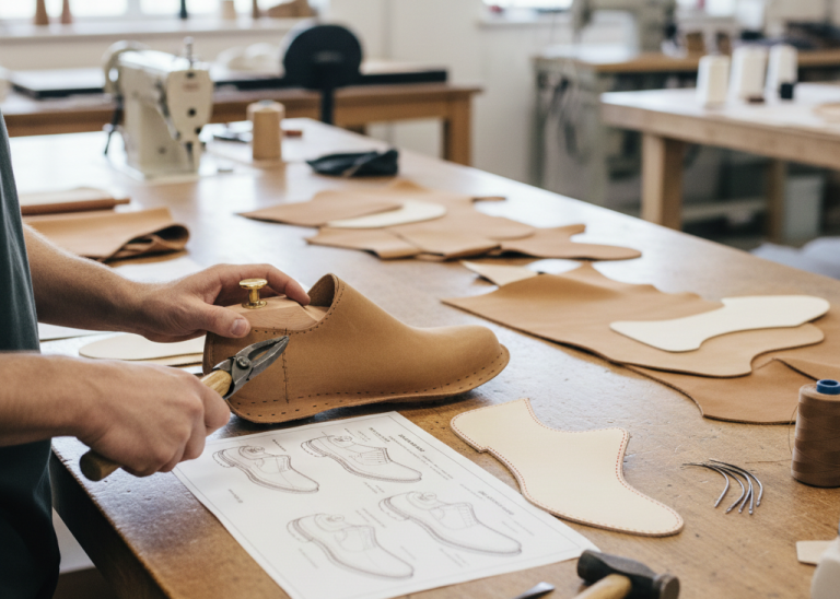
Pattern Flattening
Then, fix the pattern at the marked crossing points using a needle. Start from the toe and transfer the shape point by point toward the break line. Finally, once the flat pattern is complete, add allowances to prepare the pattern for production.
This structured modelling approach improves balance, fit, and manufacturability in boot production
Posts you may like

Foot and Leg Measurements
Foot and leg measurements form the foundation of accurate boot fitting, shaft balance, and wearer comfort. The following measurements are presented directly for US Women’s Size 6 and are intended for use in boot pattern development and grading reference.
All dimensions are given in millimetres (mm) and follow standard anatomical reference points used in ladies’ boot manufacturing.
Foot & Leg Measurement Table – US Size 6
| Measurement Description | Measurement (mm) |
|---|---|
| Joint girth (E) | 215 mm |
| Short heel girth (D) | 356 mm |
| Leg girth at 25% knee height (C) | 227 mm |
| Calf girth at 72% knee height (B) | 352 mm |
| Knee height (A) | 368 mm |


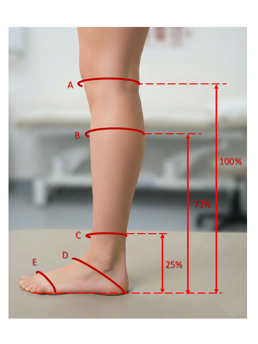
Measurement Reference Points
- Joint girth: Circumference around the ball area of the foot
- Long heel girth: Measured from instep around the heel
- 25% knee height: Lower leg girth near the ankle–calf transition
- 72% knee height: Maximum calf circumference
- 100% knee height: Vertical height from ground to knee level
Using percentage-based leg measurements ensures that shaft proportions remain anatomically correct across sizes and styles. The Given data will vary based on the type of shoes, construction and material.
Application in Boot Manufacturing
- Maintains consistent calf fit and shaft balance
- Reduces tightness or excessive looseness in high boots
- Improves comfort and wearability
- Minimizes fit-related rework during sampling and production
Key Takeaways for Footwear Professionals
- Accurate pattern modelling defines the visual balance and manufacturability of boots
- Insert-based constructions improve design flexibility and seam reduction
- Correct foot and leg measurements are essential for reliable shaft fit
- Percentage-based measurement points ensure anatomical consistency
Together, these practices form a strong technical foundation for successful boot development.